Base: A New Definition
Mitochondria: Aerobic Engines
Stripped Down
More
Zipp 808 vs TriSpoke
Wheels
Forks
Aero Bars
Frontal Area
Skinsuits
More
Roller Crr Data
Tire Wear
Project: Rolling Resistance
More
Stems
Power Meters
Wheels
More

Stem Evaluation Methods 


Mass, stiffness, durability, and price were measured for each stem tested.


Mass


 Every component on the stems was measured using the same digital scale (model, serial).  The principle components were the faceplate, faceplate screws, extension body, steer clamp screws, and the steer tube shim.


Stiffness


Stiffness is defined as the load to deflection ratio.    The 
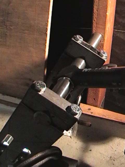
loading condition was a combined mode, meaning that a +/- horizontal/vertical load was applied concurrent with a small bending moment (load was applied 85 mm off of the handlebar clamp centerline).  This combined mode is consistent with how stems are loaded during any out of the saddle effort such as climbing or sprinting.


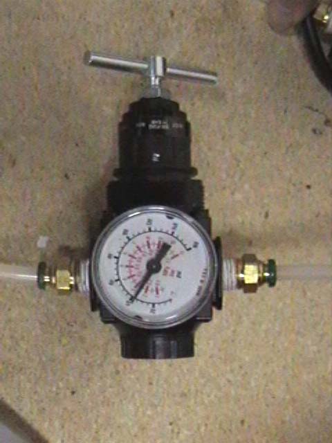
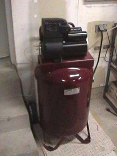
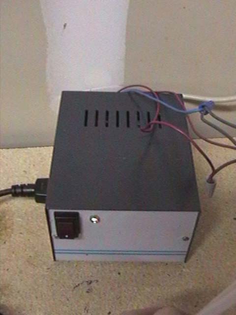
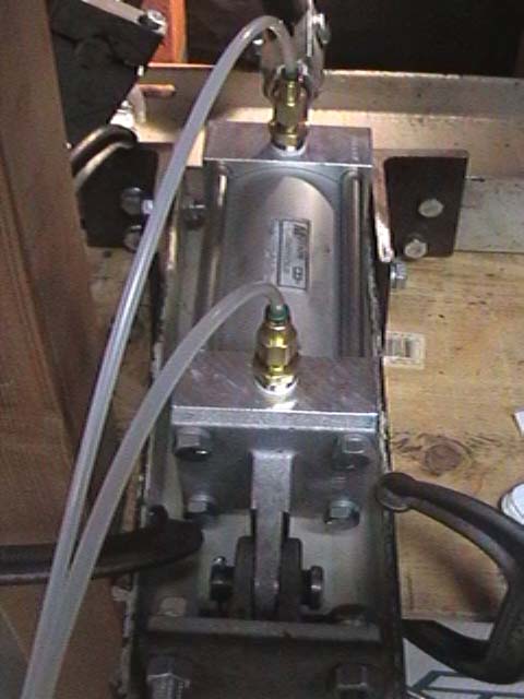
The load was varied using an air cylinder in 5 psi increments as adjusted through an analog air pressure regulator (model).  Using specifications provided by the air cylinder manufacturer, the air pressure values could be 
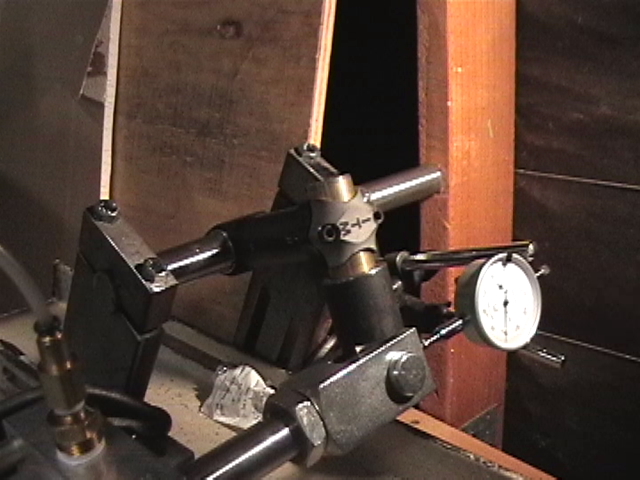
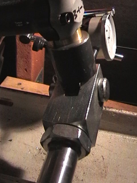
converted to a load.  Deflections were measured along the same axis as the load was applied using a dial indicator.


At each stage of the durability testing, static stiffness measurements were made.  The many data points taken allows for a statistically better measurement as random errors associated with manually adjusting air pressure or reading the dial indicator were minimized.


Although the combined loading produces a rotational/torsional component of displacement, only the translational movement along the axis of the applied load was measured.  Consequently, the stiffness measurements that are reported are not entirely representative of the physical phenomena at work – it is a simplification that is extremely repeatable, however.


 The raw data was averaged, plotted two-dimensionally, and then linearly regressed (a straight line was fit to the data).  The resulting slope of the load-deflection curve represented the stiffness of the stem specimen. 


Durability


Using the same two loading configurations in the static stiffness tests described above, the loads were cycled in the positive and negative directions according to the following schedule:


Extreme Durability


In order to ensure that all stems were tested to failure, the following schedule was followed after the initial durability testing phase was completed.


At the heart of this test is a fixture that uses some creative engineering to accomplish the task.  Below is a schematic of the fixture setup, which illustrates its key features. 


Air compressor


The compressor is the engine of the system.  An electric motor drives a piston, which charges the main cylinder up to 125 psi.  This reservoir then provides the necessary compressed air to supply the air cylinder on the test fixture.  Analog air regulators control the individual air pressure to each of the solenoid valves.


PC and parallel port control box


A friend of the cause designed the parallel port control system that allows the load cylinder to be cycled in both the positive and negative directions.  The control box houses the relays that drive the solenoids.  The relays interface with an old school IBM thinkpad laptop computer.  A simple program written in qbasic toggles an electric pulse to the relays – when the relay sees this signal it closes the circuit and sends a larger electric signal to the solenoid.


Solenoids


The solenoids are simply valves that are electrically controlled.  They can be toggled to be either open or closed.  In the closed position, the air supply from the compressor is cut off from the load cylinder and the compressed air that was previously in the cylinder is vented out to the atmosphere.


Load Cylinder


This cylinder has a 3.5 inch piston diameter and has air inlets on opposite sides of the piston.  Depending on which side is energized with compressed air, a load is generated in either the positive or negative direction.  The cylinder has pinned boundary conditions on both of its attachment points which ensures that the load is applied along one axis and it also helps prevent cylinder damage due to bending loads.


>>MORE